In this section, I want to log the building of the Serial Communication Interface board for the Z80 computer.
First we want to check if all the components are there.
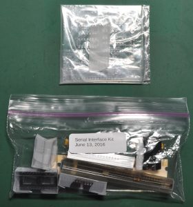
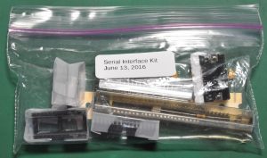
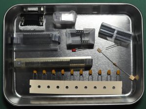
It comes in two pack of bag contains all the needed components and the PCB.
Let’s unpack and check if all needed components are there
It looks like there are no sockets provided for the ICs so I will add those sockets from my own parts inventory. I also plan to use socket for the crystal for future replacement when needed.
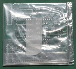
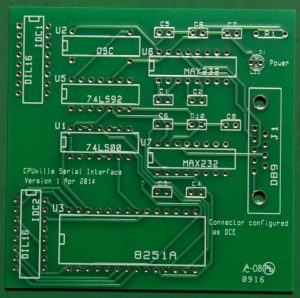
Now, let take a look at the PCB.
As other boards, this board is also look very nice. One minus point is there is no hole for us to fit this board on a case or acrylic board.
Now let’s go for soldering !
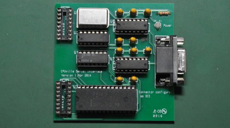
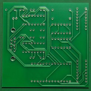
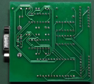
Here is the finished board without all the ICs implemented. On the left is the bottom side, washed.
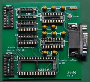
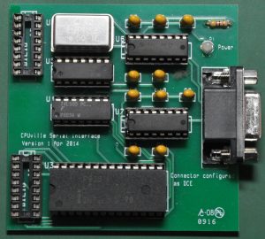
Here is the finished board with all the components implemented.
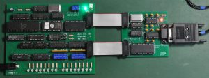
Now it is time to connect to the CPU board and make some tests.
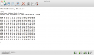
After connecting to the CPU board, set the clock mode to fast clock, and set the start address to 0x04C0 (00000100 11000000). This is the warm start of the monitor program. Connect to the computer via serial cable and configure the setting to 9600/8/N/1 . After setting the address then set the reset to off. Now we can see the prompt at the console terminal.
I am using the RS232C to USB adaptor and it works fine.
From here we can run commands like dumping the memory for a location, load hex file to the memory, load binary from memory to PC, etc.
I am planning on learning how to make my own monitor program with z80 assembler, and learn how to interface with the 8251 serial chip. I think this is the basic to learn how to program the serial monitor, further programming own bios for a computer.


