I will assemble the backplane-8 for this computer project.
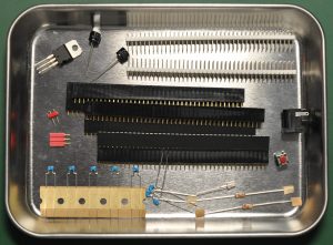
The components are just the sockets and several capacitors and resistor, plus the reset button. I have replaced some of the components with my own components due to personal preferences. I changed the tact switch for reset with the red color, put sockets on the voltage regulator footprint so for later project I can change the regulator to whatever it needs for more current etc. Then I have add the jumper pin so that I can choose to use a regulator or directly power this backplane with 5v. I also add two capacitors for the regulator. I choose the low profile one to make it look nicer.
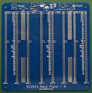
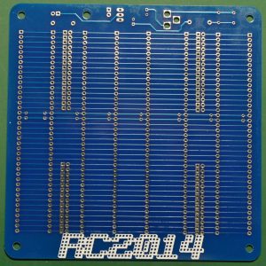
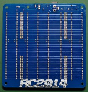
Here is the bare board of the backplane. The board is quite thick comparing to other PCB and the quality is excellent. Now time to do the soldering.
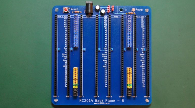
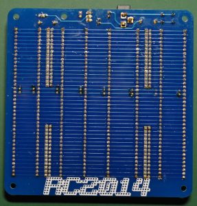
Now I have finished soldering, above is the finished board. On the left is the board before cleaning. As you can see, flux is everywhere on the board. It looks dirty and sometimes it will give some issue when the computer running. So on the right is the board after cleaning process. It looks nicer.
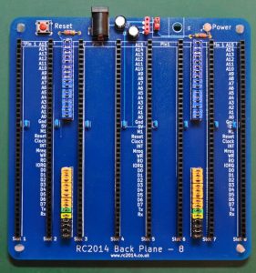
Here is the finished board, with the jumper inserted. I have use multiple colors of jumpers so that I can simply identify the line when I want to disable some bus line in the future project.
Well, that’s all for the backplane 8 assembly. It’s very straight forward. It took some time for me to assemble as I want to assemble it right and pretty, with all the components aligned well. I will update when I add something new with this backplane.


