The last time I build the Digital I/O Module for rc2014, it is version 2.0. In that version, the addressing logic is not tight enough. So I have decided to build the current version, 2.2. I have ordered this kit on January 2018, but got a lots of work to do so it has been some time to work around with this module.
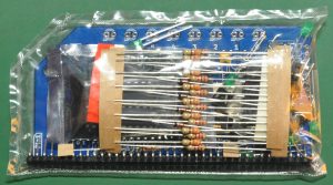
As usual, well packaged.
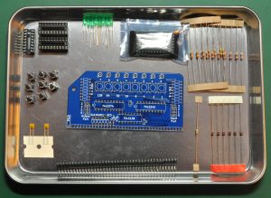
These are the components in the packages. It looks familiar with the previous version, except there are some diodes added. Looks straight forward to solder.
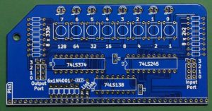
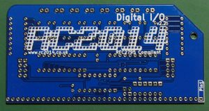
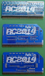
Here is the pcb. As always, very nice designed pcb.
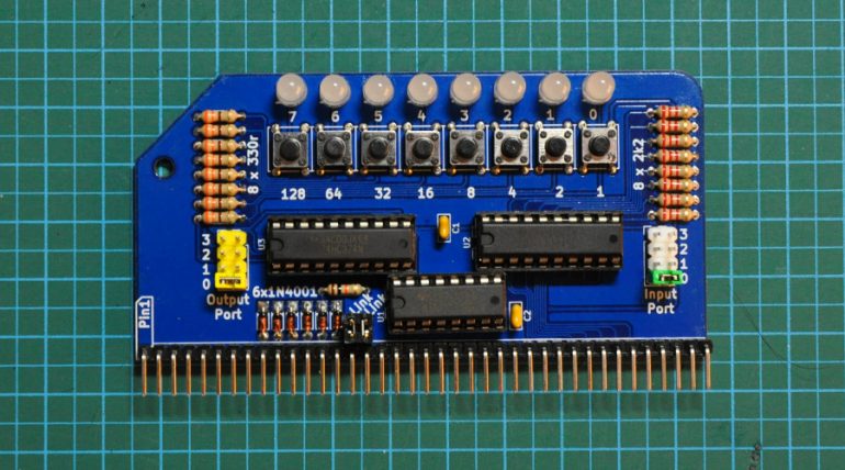
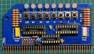
Finished soldering, looks very nice. I try to solder and aligned the components as nice as possible. I choose to use the moody color of led’s this time, can’t wait to test it.
Here is the module with all the ic’s implemented. Just 3 ic’s, not much. Just set the address to port 0 for both input and output. We can set the port number to 0,1,2,3 for both input and output. Let’s see how it works !
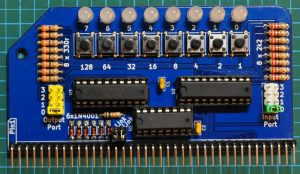
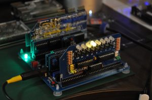
Here we are, the module in action ! It’s really looks cool, isn’t it ? I ran a few tests on changing the address of the module. I set the input to another port number and it works well, but got some problem with output port other then 0. I don’t know what is the bug right now, but it don’t work as expected on other port then 0. I just changed the port number to whatever I set in the basic program but I just don’t work as I expected. I will do the debug then.
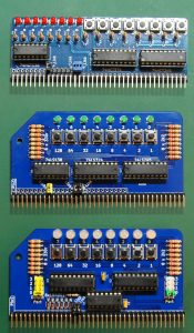
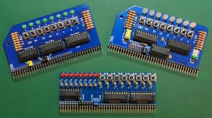
Conclusion, really nice module to test, play and learn for, I have all 3 versions of rc2014 I/O modules here. I just took a shot of those three revision so we can compare. Well, as I can say, the module is better designed as the revision increased.
As always, I really enjoy playing and learning with rc2014, and I will explore more from now. In fact, I am on progress learning about computer from the low level, so a good start with rc2014. Thank you Spencer, for creating this nice computer. I just say, I really a big fan of rc2014 !


