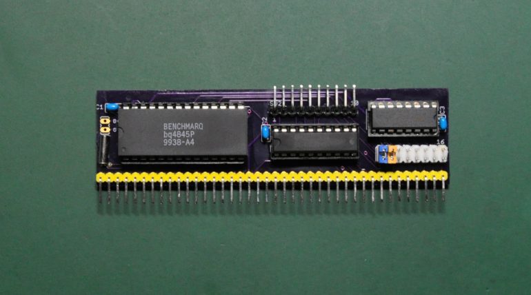
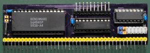
As I want to read time/clock data from my RC2014, I think I need a module with RTC chip on it, so I considered to build the RTC board for my RC2014. This board is designed by Dr. Scott M. Baker and the original info can be found from Dr. Scott blog [Z80 Retrocomputing 2 – Real Time Clock for the RC2014]. I have the board manufactured by OshPark with Electroless Nickel Immersion Gold (ENIG) finish.
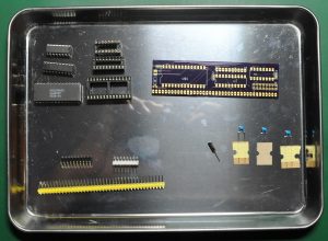
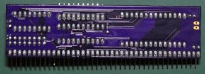
Here is the PCB, looks very nice and professional. Now I want to search my inventory for the components needed.
Looks like there is not much components to solder, so let’s get the board done !
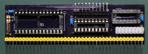
Here is the finished board. I have cleaned the PCB with flux remover and alcohol. Not it’s time to implement the IC’s.
Here is the board implemented with all the chips and ready to go !
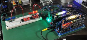
As we can see in above picture, I have set the RTC chip address to port C0, and the output pins to address E0. I have tried to do some effect by reading the clock data from the RTC and put the output to two digital I/O module and some LED’s via output port on address E0. I work nicely and awesome.
In further project, I would like to read the clock data and output it to some Nixie tube, or some 7 segments display driven by some shift registers.


