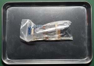
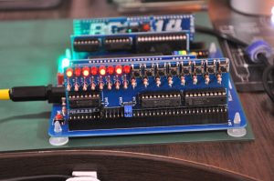
I have bought another additional board with my RC2014 kit that is called Digital I/O module. It have 8 led’s and 8 tact switches for input and output purpose. Here is the package that I received.
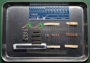
All the components are there, I just replace the LED to the red color, personal preference. I want to try to make the Knight Rider scanner effect later, so red will be nice, I think.
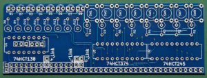
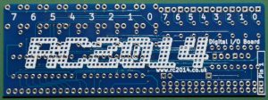
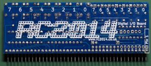
Here is the board included. As other boards, very well fabricated and nice design.
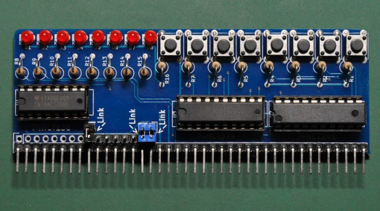
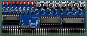
Here is the finished board. Look very nice. It take some time to align the resistor properly so it looks nice. I have cleaned the solder flux on the solder side of the board and it’s ready to go !
As I learned from the schematic, this module didn’t have address decoding well. We can access this module on address 00, 04, 08, 0C, 10, 14, 18, 1C, 20, 24, 28, 2C ……. 70, 74, 78, 7C sequence. I think we should make the address decoding more strict in the future version.
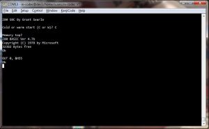
Now it’s time to test the board. I hooked up to the one slot of the backplane and turn on the power. Everything looks ok, no ‘Magic Smoke’ appears. The Microsoft basic boots fine. Now, try to lid up the LEDs.
We can light up the led by setting some data to port 0 (or else, as I mention above). Above I try to set the port 0 to 55h.
We can also read from the tact switch, just do IN (0). One thing that I discover is the led are lined in backward, that means the LSB is on the left and the MSB is on the right. So if we put 01h on port 0, the very left led will light up.
Conclusion
I am happy with this module as I can test the rc2014 to see if it works or not. It looks like the I/O is work well. I think I will make use this module in other future project, not decide what to do next yet. Hope can give somebody hint on what this module do.


